
ATS for PCB Testing: A Revolutionary Software By Su-vastika To Check TP Points Of PCB
Most people experience a fearful heartbeat skip when the word “test” is mentioned. Taking an exam has a certain daunting quality that appears to have been ingrained in us since our first days of elementary school. But everyone is aware that testing is a crucial aspect of life. The thought of a surgeon brandishing a knife while failing his fundamental anatomy class should frighten everyone, just as you wouldn’t want to ride on a plane with a pilot who failed her flight examination.
Testing is required for the circuit boards we create as well, and in their case, the testing will reveal how properly they were produced. The board needs to be set up with particular components that a test probe may reach in order for this testing to take place. Test points are these components, and it’s crucial that PCB designs have them.
Power backup and energy storage solution provider company, Su-vastika, has developed a PCB testing jig, ATS for PCB Testing, that can be used to test any PCB inside the inverter/UPS.
In this article, we will guide you through the working of our automatic PCB testing jigs and how they will make the test point checks of any PCB a super simple task.
As soon as you open the test automation program file, a Su-vastika logo will appear, following which a black screen or command screen and a QR code login screen will open, as you can see below.
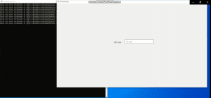
Once these screens are open, proceed to scan the QR code of the PCB with the scanner or enter the QR code manually. A test window will open at this time where you will be able to view Select Test program, Start Time, End Time, NEXT PCB, among others.
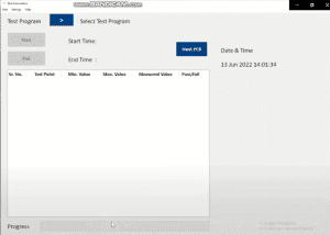
Select the test that you want to carry on using the dropdown menu and proceed to manually enter/scan the serial number according to your PCB card.
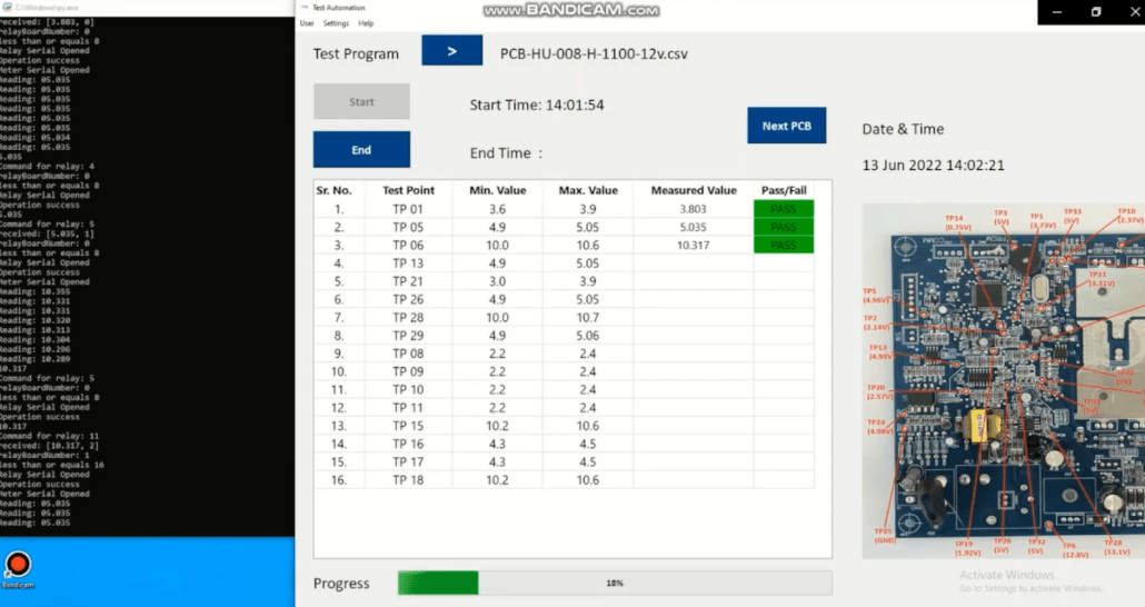
At this junction, you will also be able to see the minimum and maximum values for each test point.
If the measured value comes between the middle of the mime and the maximum value range, the status will show a pass. Otherwise, it will show fail.
Now, it’s time to run our test, whose progress you can see at the bottom of your screen.

As you can note, the test has started as the software will check through each TP point one by one, whose progress you can also see in the black command screen on the left. Taking about the command screen, it has designed to show you the relay serial number, the relay which got the command, which relay is connected to which board number, the inputs it has received, the success or failure of the operation, the open & close status of meter serial, and whether the reading was successful or not.
Based on these tests, a pass or fail value will appear against each test point. For example, in the below image, you can see as the testing point for TP 01 came out to be 3.803. Since it is in the range of 3.6-3.9(minimum and maximum value), it is showing a pass status. The progress meter will also keep on increasing until it reaches 100%. At the end of the test, you will able to see the start and end time of the test and keep it for future records.
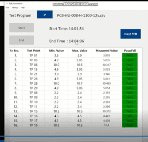
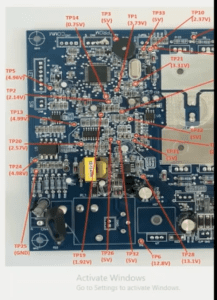
Our new software has been designed to automatically check all the testing points of our PCB card in a quick and efficient manner. These results will also give you a deeper insight into the voltage (in wattage), range of individual test points, and the measured value of each test point. You can refer to the image below for an accurate reference of the test points.
Leave a Reply